
RTK-GPS coordinates
Published:
RTK coodinates
GPS coordinates
GPS coordinate system enables every location on Earth to be specified by a set of numbers, which may be expressed in a combined three-dimensional coordinates. The GPS solution (SPP or SBAS) is expressed in the frame of Earth Centered Earth Fixed (ECEF) or geodetic frameLogitude Latitude Height (LLH). The origin of the geographic frames are defined in a calibrated datum. The most common used datum is WGS84, which defines the approximate shape of the earth, location of the earth center, equator (latitude 0 deg) and meridian (longitude 0 deg). The coordinates of ECEF and LLH can be transformed mutually in the same datumn. The Real Time Kinematic (RTK) provides the solution in a local tangent plane coordinates (LTP). The tangential point (origin of LTP)locates at the base station of the RTK system. The base coordinates is ususally pre-measured and calibrated. Ntrips service one of the service to provide the , the reference frame of the geodetic coordinates of the base caster can be found on unavco.
ECEF and LLH
ECEF (acronym for earth-centered, earth-fixed), also known as ECR (initialism for earth-centered rotational), is a geographic and Cartesian coordinate system and is sometimes known as a “conventional terrestrial” system. It represents positions as X, Y, and Z coordinates. The point (0, 0, 0) is defined as the center of mass of Earth, hence the term geocentric coordinates. 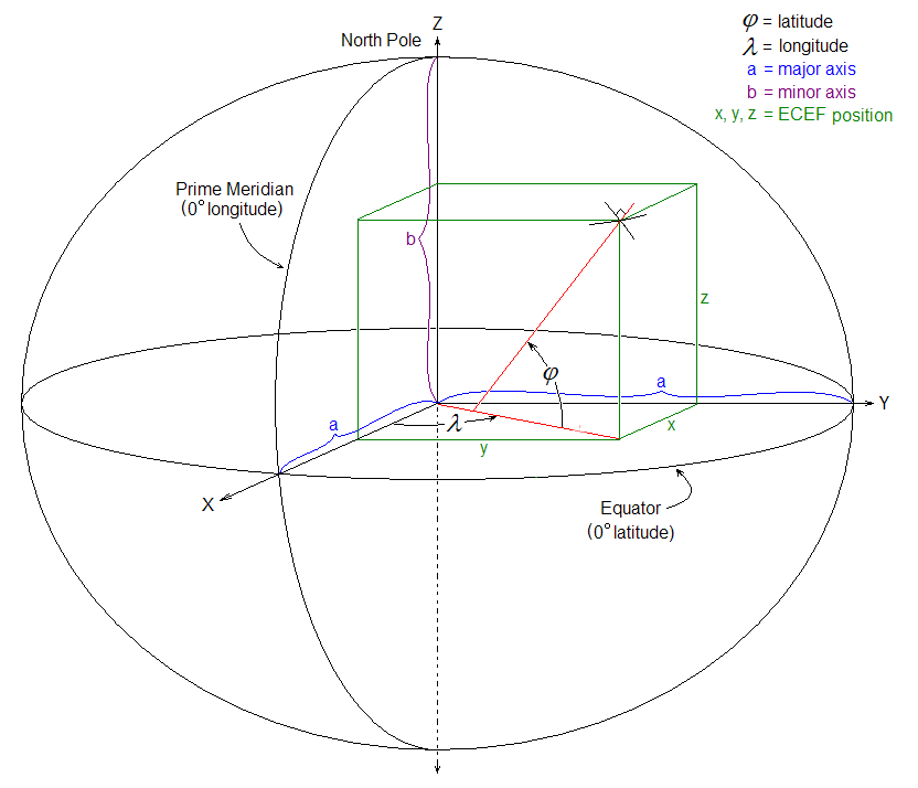
Geodetic coordinate is composed of latitude ($\phi$), longitude ($\lambda$) and height. For WGS84 datum, the 0° parallel of latitude is designated the Equator, the fundamental plane of all geographic coordinate systems. The “longitude” of a point on Earth’s surface is the angle east or west of a reference meridian to another meridian that passes through that point. The elevation above the ellipsoid (ellipsoidal height) is the elevation above a mathematical model that approximates the shape of the earth which is also approximately defined in WGS84.
NED
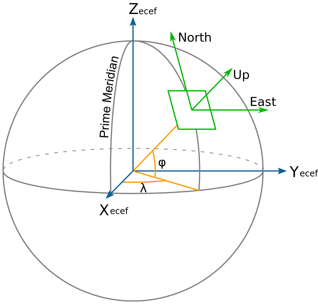
A local tangent plane can be defined based on the vertical and horizontal dimensions. The vertical coordinate can point either up or down. There are two kinds of conventions for the frames:
- East, North, up (ENU), used in geography
- North, East, down (NED), used specially in aerospace The solution of RTK is expressed as a baseline vector starting from the geodetic coordinates of the base station to the rover. The relative error of rover to the base is in centimeter level. However, the accuracy of the coordinate of rover in the geodetic frame or ECEF depends on the accuray of base station on the earth frames.
UTM
The Universal Transverse Mercator (UTM) and Universal Polar Stereographic (UPS) coordinate systems both use a metric-based Cartesian grid laid out on a conformally projected surface to locate positions on the surface of the Earth. The UTM system is not a single map projection but a series of sixty, each covering 6-degree bands of longitude. Hence, UTM is a 2D frame.
Transformation of coordinates
The transformation between ECEF and LLH is straightforward, but the transformation between LTP and the earth frame needs to specify the origin point of the LTP. Therefore, if the origin of LTP exists some error, the bias of transformed coordinates will be introduced in the localization result. Therefore, this RTK solution is called “pseudo-absolute” position solution.
Affecting factors of RTK solution
1. Base station coordinate accuracy
The base station coordinates should be known to within 10 m in the WGS-84 datum for optimal system operation. Incorrect or inaccurate base station coordinates degrade the rover position solution. It is estimated that every 10 m of error in the base station coordinates introduces one part per million error in the baseline vector. This means that if the base station coordinates have a height error of 50 m, and the baseline vector is 10 km, then the additional error in the rover location is approximately 5 cm, in addition to the typical specified error. One second of latitude represents approximately 31 m on the earth surface; therefore, a latitude error of 0.3 seconds equals a 10 m error on the earth’s surface. The same part per million errors apply to inaccuracies of the base station’s latitude and longitude coordinates.
2. Number of visible satellites
A GNSS position fix is similar to a distance resection. Satellite geometry directly impacts on the quality of the position solution estimated by the receiver. The Global Positioning System is designed so that at least 5 satellites are above the local horizon at all times. For many times throughout the day, as many as 8 or more satellites might be above the horizon. Because the satellites are orbiting, satellite geometry changes during the day, but repeats from day-to-day.
A minimum of 4 satellites are required to estimate user location and time. If more than 4 satellites are tracked, then an over-determined solution is performed and the solution reliability can be measured. The more satellites used, the greater the solution quality and integrity.
The Position Dilution Of Precision (PDOP) provides a measure of the prevailing satellite geometry. Low PDOP values, in the range of 4.0 or less, indicate good satellite geometry, whereas a PDOP greater than 7.0 indicates that satellite geometry is weak.
Even though only 4 satellites are needed to form a three-dimensional position fix, RTK initialization demands that at least 5 common satellites must be tracked at base and rover sites. Furthermore, L1 and L2 carrier phase data must be tracked on the 5 common satellites for successful RTK initialization. Once initialization has been gained, a minimum of 4 continuously tracked satellites must be maintained to produce an RTK solution.
When additional constellations such as GLONASS are tracked, one of the satellites will be used to resolve the timing offsets between that constellation and the GPS constellation. Tracking additional satellites will aid in the RTK solution.
3. Environmental factors
Environmental factors that impact GPS measurement quality include:
- Ionospheric activity
- Tropospheric activity

- Signal obstructions
- Multipath

4. Operating range
Operating range refers to the maximum separation between base and rover sites. Often the characteristics of the data link determine the RTK operating range. There is no maximum limit on the baseline length for RTK with the receiver, but accuracy degrades and initialization time increases with range from the base. The rule of the thumb is as mentioned above very 10km more, the localization error of RTK will increase around 1cm.
Localization with two GPS for mobile vehicle
The mobile vehicle is assumed to be a rigid body in 3D space, hence the pose of the vehicle includes the coordinates of one point on the vehicle in the map frame (NED) and the heading angle of the mobile vehicle. One way to get these two elements is to install two GPS modules on one mobile vehicle. One GPS device is called reference module corrected by a base module (from Ntrip caster or self-built base station), while another GPS device is called attitude module corrected by the reference module. Basically, the baseline vector (heading) is obtained by the differential solution of the two GPS pair, while the position of the reference module (fixed on the vehicle) is obtained in NED with the origin of the static base. In this way, we can obtain a complete pose result of the vehicle in the built NED frame.